
Example 2 – A bathroom with an in-wall carrier
What it is about
The bathroom on the 2nd floor of the sample plan: an in-wall carrier at the outside wall, on the right the shaft with the stack, the lavatory on the left, the toilet in the middle. You work on the In-wall carrier routing palette page; LuaCAD calculates the elevations from the centerline elevations of the fixtures.
The steps and why in this order
- Insert the stack – with a distance to the wall.
- Insert the fixtures – toilet and lavatory.
- Draw the carrier line – the line of the in-wall carrier.
- Place the vent – a stack up at the end of the line.
- Generate 3D and read the findings.
- Build the relief vent with fittings by hand.
The stack is the start of the network, the fixtures give the elevations, the line connects both. "Generate 3D" calculates all parts from them and sizes them by the standard. Only then comes what "Generate 3D" does not build – the relief vent by hand. Annotating and the list work as in example 1.
1. Insert the stack
The stack in the shaft takes the horizontal branch of the in-wall carrier.
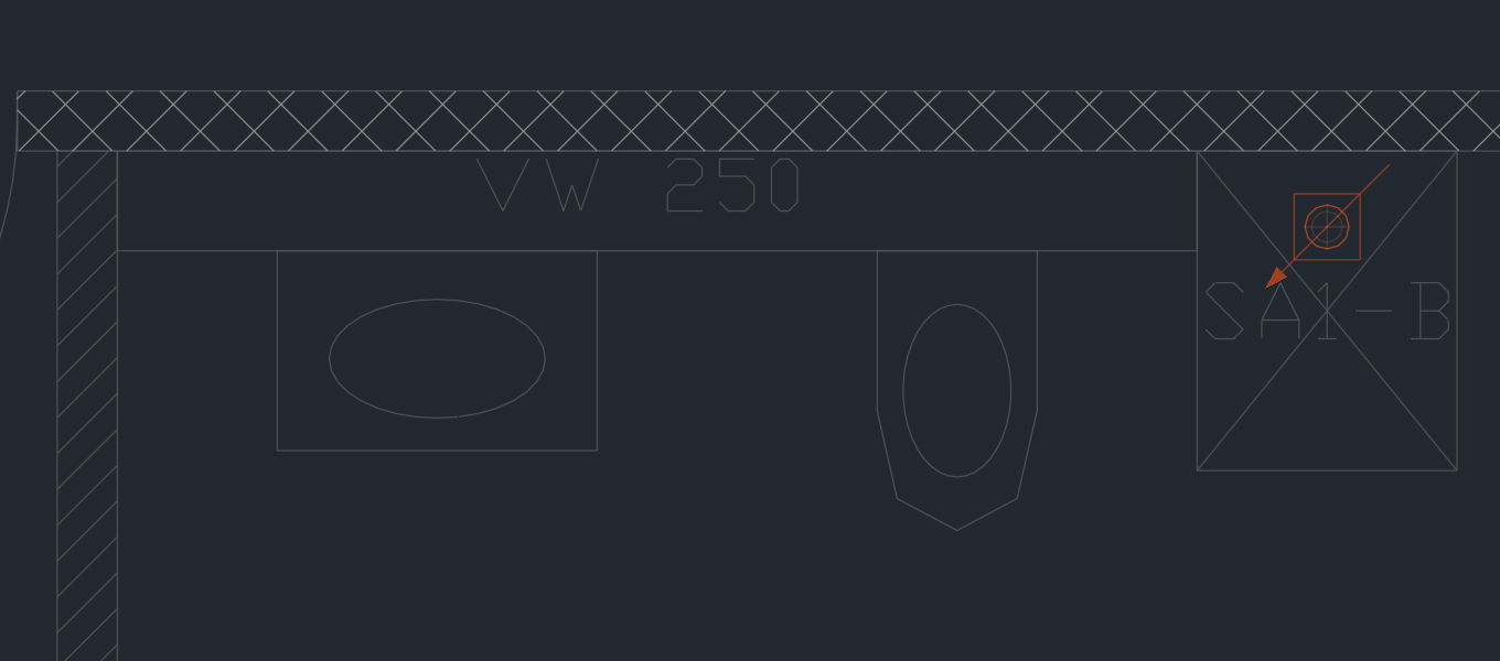
- Under 1 Stack choose the DN (110) and the product line.
- Click the Stack tile, press A and click a wall corner of the shaft; in the dialog box type X and Y to the middle of the shaft (Enter distance).
- Click, then Enter.
More details
The stack then stands exactly in the middle of the shaft, without measuring. With the check box Stack dialog box when inserting the dialog box follows: leave connector "wye 88½°", continuation above and below "pipe".
| Key | Effect |
|---|---|
| A | distance to a reference point, for example a wall corner: amounts X and Y |
| Space | with a distance: next base point, the distance stays |
2. Insert the fixtures
Toilet and lavatory set the elevations of the pipe with their centerline elevation.
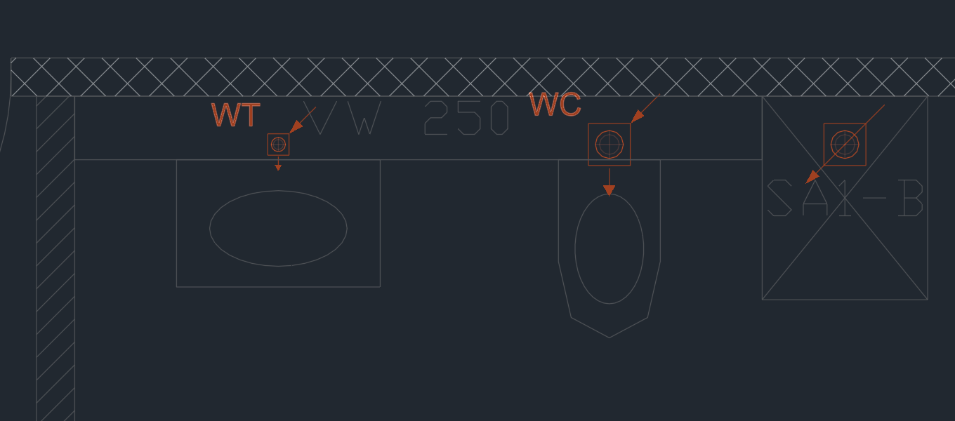
- Under 2 Fixtures choose "toilet" in the Fixture list, click the Fixture tile and place the toilet with A (Enter distance) in the middle of its niche 2.
- If the arrow 3 does not point into the room: R. Then Enter.
- Insert the lavatory the same way 1.
More details
With the check box Connector dialog box when inserting the fixture dialog box follows: for the toilet centerline elevation 230 above FF, main fitting "toilet connecting bend (with coupling)"; for the lavatory centerline elevation 550 above FF, main fitting "trap connecting elbow". The fixtures still stand free; the line in the next step connects them.
3. Draw the carrier line
The carrier line connects stack and fixtures – the horizontal branch later lies along this line.
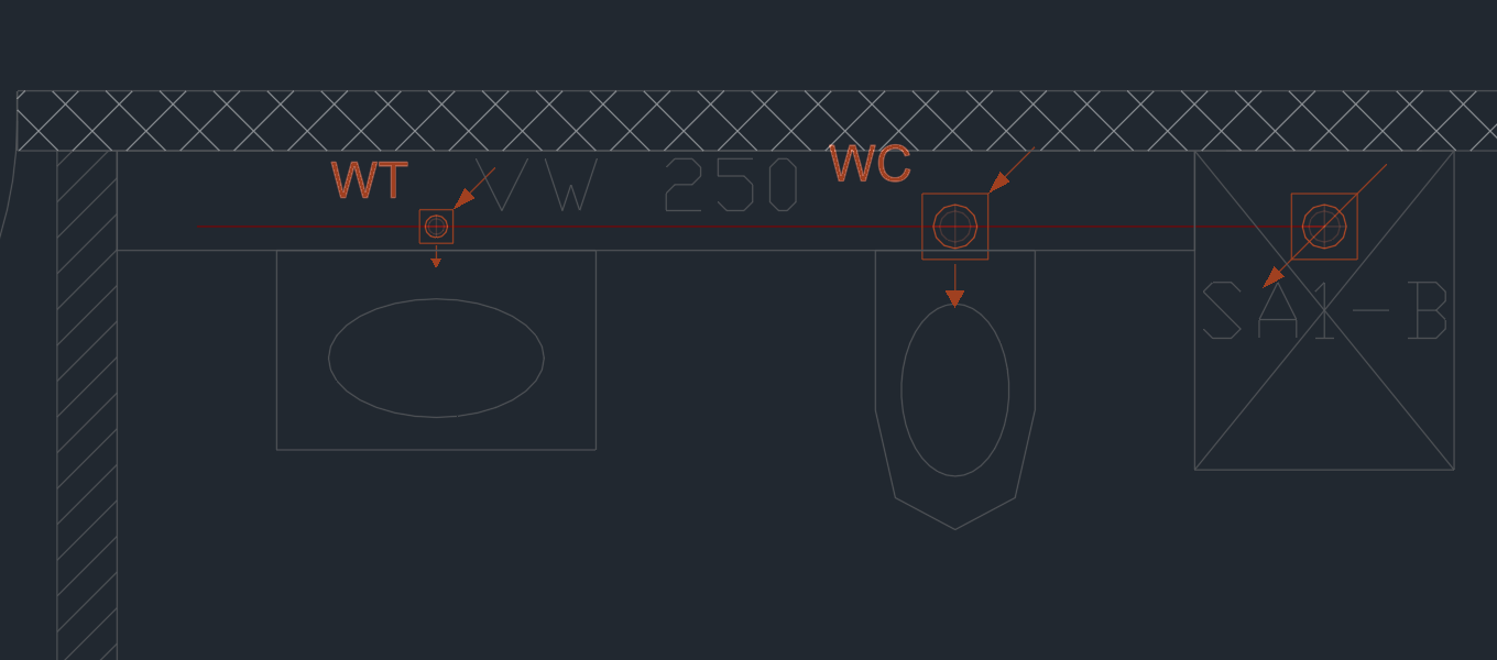
- Under 3 set the slope, here 1.5 %.
- Click Insert line, start at the stack 2 and draw the line through the connectors.
- Continue a little beyond the lavatory 1, Enter.
More details
The slope is always in %. The line snaps above every fixture. The piece beyond the lavatory is needed for the vent in the next step.
| Key | Effect |
|---|---|
| A | slope and elevation (Carrier line) |
| Space | snap to angle / free |
4. Place the vent
If the pipe is long or carries many fixtures, it needs a vent – a stack up at the end of the line.
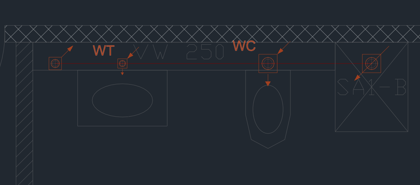
- Under 1 Stack click the Stack up tile.
- Click at the end of the line 1 – it snaps there; Enter.
- In the dialog box of the stack up: diameter 75, top from TOS == 1100, calculation "Vent (no load)".
More details
The horizontal branch in the in-wall carrier falls with the slope of the line toward the stack. How high it lies, "Generate 3D" calculates from the centerline elevations of the fixtures: the highest point is the end of the line, from there it falls 1.5 cm per meter. The diameter 75 is the diameter of the fixture drain. More: Stack up in the in-wall carrier.
5. Generate 3D and read the findings
Stack, fixtures and line become the stack pipe, the horizontal branch and the connecting parts.
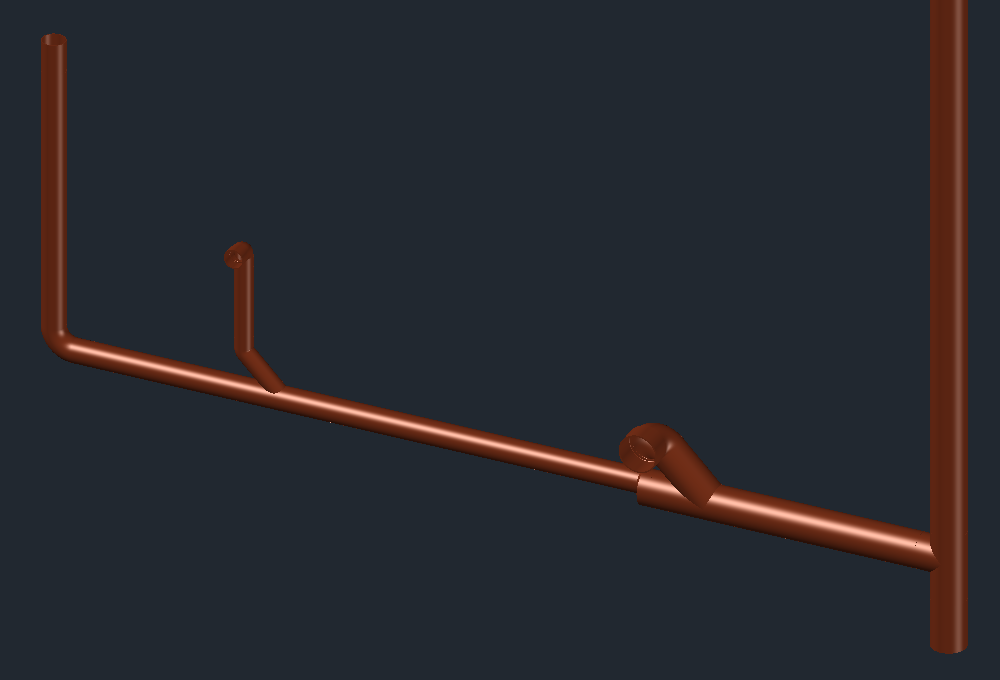
- Click Generate 3D (step 4) and click the stack – or Enter for all networks.
- If there is something to say, read the result – Show shows the place.
More details
LuaCAD calculates the elevations, sizes by the standard and places pipes and fittings. The result shows errors in red (also as a marker in the drawing), notes in orange, below the sizing per section.
6. Build the relief vent with fittings by hand
"Generate 3D" does not build the pipe back into the stack – it is made from fittings by hand, which stay the next time you generate.
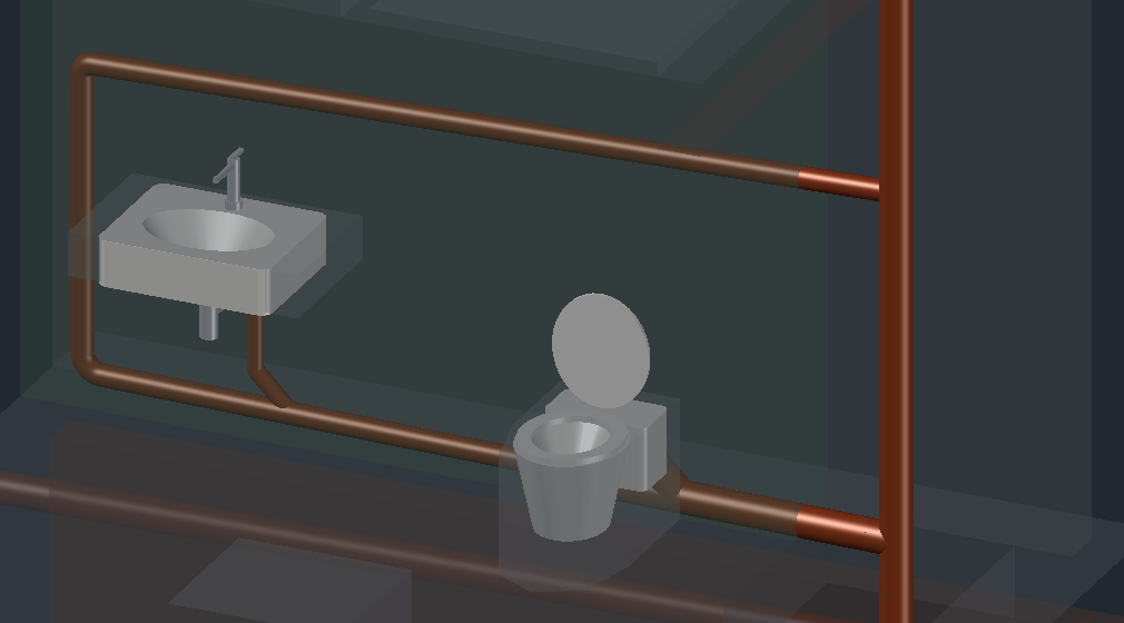
- Fittings page, Single: elbow 88½°, dimension 75 – Insert, connect it to the upper end of the vent 5, turn it toward the stack with R, click.
- Wye 88½°, 110/75 – Insert, click the stack, slide along it to above the lavatory and click 7; turn the outlet toward the elbow with R.
- Connect two ends: click the free end of the elbow, then the outlet of the wye; accept the solution with the pipe 6 with Enter.
- Tools page › Check 3D: all parts connected.
More details
After "Generate 3D" the vent ends open above the lavatory. The wye is inserted in-line into the stack. The parts placed by hand stay when you generate the 3D again later; the sizing knows the vent through the stack up. In detail with a section: Example relief vent.
Next: example 3
- Example 3 – A horizontal branch: in the basement collect the stacks from several shafts and lead them to the sewer.
- Annotate and output the bill of materials: as in example 1, step 7.