
Example 1 – Water for an apartment
From the empty floor plan to the finished riser diagram: apartment A2 on the 1st floor of the sample project, the plumbing drawing of this level. Cold water, hot water and recirculation run along the wall in the corridor and below the heating into shaft SA2-B of the bathroom; there they join the risers that go through the levels. From the shaft a manifold in the bathroom feeds the fixtures through flexible PEX pipes. One sentence, one picture and the clicks per step – the light blue numbers in the text are the numbers in the picture above. Variants and details are collapsed under "More".
1. Open the palette and choose the riser template
The parallel pipes and the risers take their systems and sizes from the riser template.
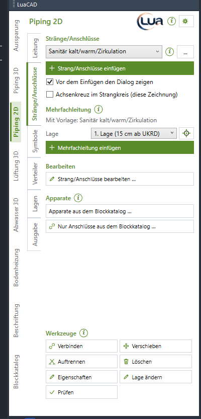
Ribbon › LuaCAD tab › Piping 2D, in the palette the Risers/connectors page.
- 1 In the list under Risers choose the template for cold water, hot water and recirculation: three pipes, cold water 20, hot water 20 and recirculation 15 mm.
- 2 You need Insert riser/connectors in step 2.
- 3 The system elevation of the parallel pipes: the 1st system elevation, 150 mm below the bottom of the slab.
- 4 You need Insert parallel pipes in step 3.
More details
- The factory system elevations are 150/300/450/600 mm below the bottom of the slab; reference level and distance are in parentheses. Create your own in the gear menu › System elevations – see Creating system elevations.
- Palette values only apply to pipes and parts you insert from now on – change existing ones with the tools.
- A single pipe instead of several side by side: page Pipe – see Inserting a pipe.
2. Place the risers in the shaft
Piping 2D draws the vertical pipes in the shaft as riser symbols: one circle per pipe, the arrow tells where it runs.

Insert riser/connectors (Risers/connectors page), then:
- In the dialog box before inserting check the direction "down" and the insulation (here 13 mm), OK.
- The risers hang at the cursor; the Space key switches the riser you hold them by. Click into the shaft, Enter.
- 1 2 3 The line lies on the diagonal according to DIN 1986-100: down = lower left, up = upper right. The arrowhead shows the flow direction – cold and hot water come up from below, the recirculation flows back down.
More details
- If the insulation circles need more room than the spacing of the template, Piping 2D increases it and says so on the command line.
- R rotates the row of risers; the arrow stays on the diagonal.
- More under Inserting risers and Choosing a template.
3. Draw the parallel pipes in the corridor
Heating supply and return lie on the 1st system elevation in the corridor. The plumbing pipes run beside them, turn above the shaft and go through the wall to the risers.
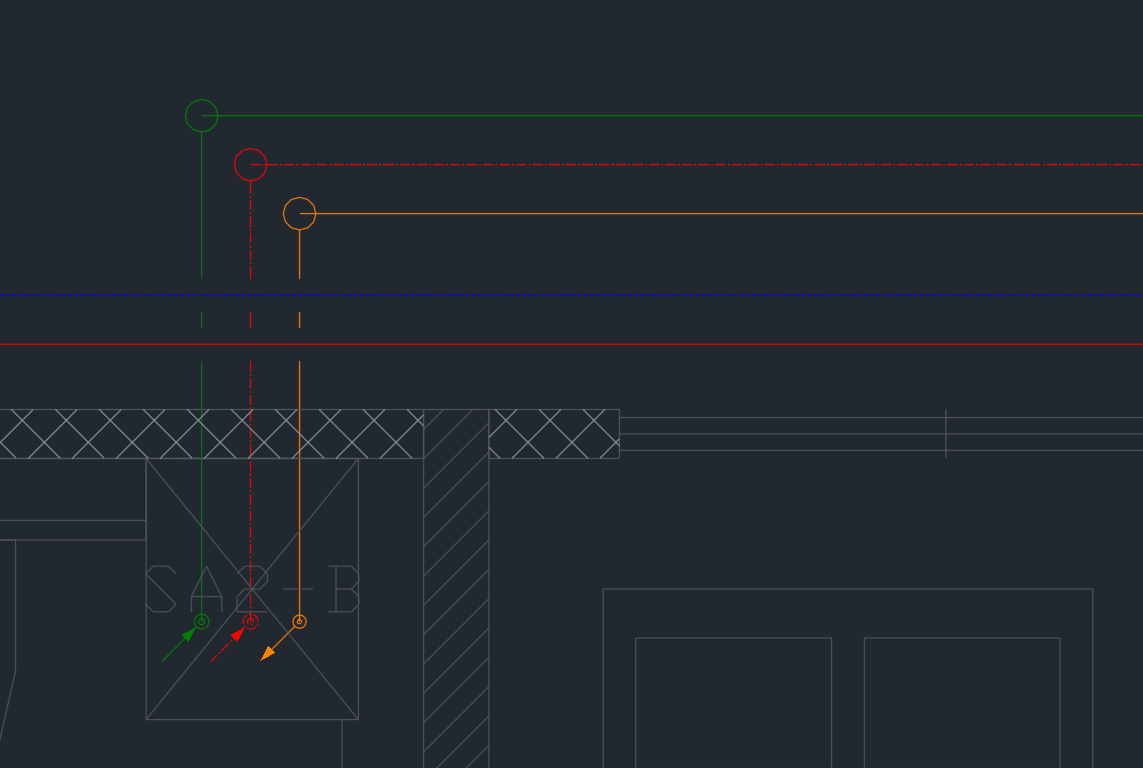
- First the heating: the riser template for heating supply and return, the 1st system elevation, Insert parallel pipes, start on the right in the corridor, click further left, Enter.
- Then choose the riser template for cold water, hot water and recirculation and click Insert parallel pipes again, OK in the dialog box.
- 1 Start on the right in the corridor and draw to the left. If the pipes lie on the wrong side of the drawn line, S switches the side.
- 2 Click the corner above the shaft, then A: in the System elevation and wall offset while drawing dialog box choose "2. Lage", OK. The circle of the elevation change appears at the corner.
- 4 Click the cold water riser in the shaft: each pipe ends at the riser of its system, the run is finished.
- 3 The pipes on the 2nd system elevation pass below the heating – they are broken there.
More details
- The dialog box while drawing is explained under System elevation, wall offset and fixed length while drawing; it also sets a wall offset so that the pipes follow a wall at a fixed distance.
- The corners of parallel pipes are mitered; flexible pipes run concentrically.
- A pipe only goes through a wall in an opening – here into the shaft.
- More under Inserting parallel pipes.
4. Look at the crossing and the elevation change
What the system elevations do in the plan shows the spot above the shaft close up.
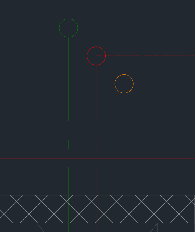
- 1 The pipe on the upper system elevation runs to the center of the circle, the one on the lower starts at the edge of the circle.
- 2 Where two system elevations cross, Piping 2D breaks the lower one with a gap – by itself, also after moving, copying or deleting.
- 3 The pipe on the upper system elevation stays whole.
More details
- If a new pipe crosses a pipe on the same system elevation, Piping 2D asks when you click (choose another system elevation or continue).
- Set the length of the gap and the size of the circle in the gear menu › Elevation marking.
- More under Crossings and Elevation change.
5. Place the connectors at the fixtures
A connector is the pipe end of a fixture: system and size come from the connector template.
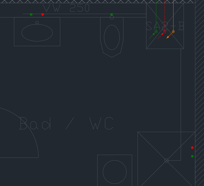
Risers/connectors page, in the list under Connectors:
- 1 Choose the lavatory template, Insert riser/connectors, click at the in-wall carrier above the lavatory: cold water left, hot water right.
- 2 The template for a wall-hung toilet – one cold water connector for the cistern.
- 3 The shower template – rotate with R to the wall of the shower and click.
More details
- Instead of connector templates: Fixtures from the Block Library places a whole 2D fixture with its connectors, Connectors only from the Block Library only the connectors at a fixture of the architectural plan – see Fixtures from the Block Library.
- More under Inserting connectors.
6. Insert and connect the manifold
The manifold sits in the in-wall carrier at the right wall of the bathroom; the risers feed it, PEX pipes go to the fixtures.
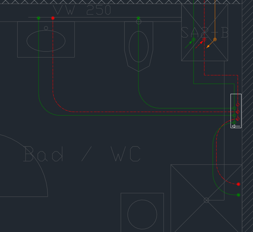
- 2 Manifold page: 1st system hot water, 2nd system cold water, 3 outlets each, With cabinet. Insert manifold, OK in the dialog box, rotate with R until the arrow points into the room, bring the supply connectors to the top with M and click into the in-wall carrier. This way the cold water outlets are at the front and the supply pipes do not cross.
- 1 Pipe page: system cold water, system elevation "2. Lage", size 20, Insert pipe. Start at the cold water riser, click two corners, end at the supply connector of the manifold – the run ends there by itself. The same for hot water.
- 3 4 5 Manifold page › Connect manifold: click the manifold, drag a window over the connectors, Enter. Piping 2D shows complete solutions; accept "geordnet, kreuzungsarm". Each PEX pipe is flexible with rounded corners.
More details
- Tab switches between the solutions, a click or Enter accepts. The command line names the crossings that cannot be avoided.
- Connect a single outlet with Connect connectors – see Connecting connectors.
- More under Inserting a manifold and Connecting a manifold.
7. Elevation symbols and elevation table
Whoever reads the plan should see on which system elevation a pipe lies.
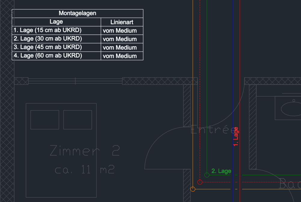
- 1 2 System elevations page › Draw elevation symbols: click a pipe, drag the symbol to its place and click. It shows the abbreviation of the system elevation in the color of the pipe. The same at the PEX pipe to the toilet – it reads "2. Lage".
- 3 Output page › Elevation table: click the corner in the corridor. The table lists each system elevation with its reference and linetype.
More details
- With one stroke across several pipes you place several symbols at once.
- Instead of the abbreviation the symbols can show slashes – gear menu › Elevation marking.
- More under Elevation symbols and Elevation table.
8. The bill of materials
The quantities of the plan as a table next to the floor plan.
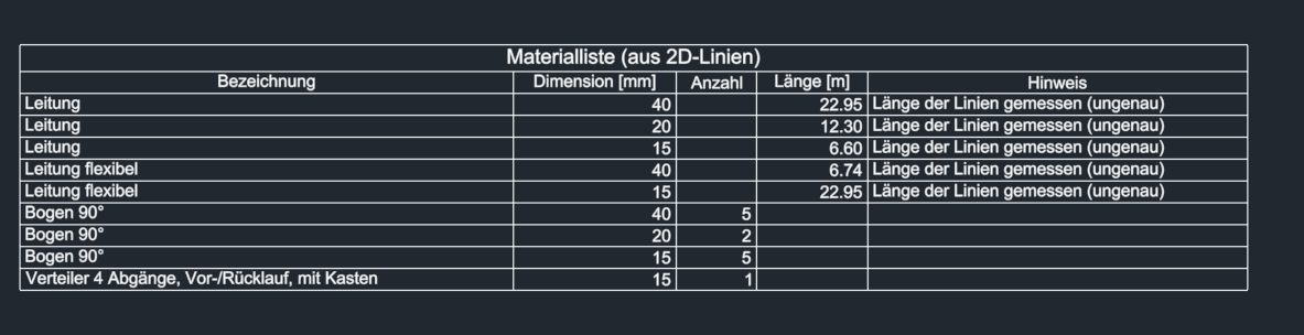
Output page › Bill of materials: the table hangs at the cursor, click next to the floor plan.
- 1 Pipes with their length per size – here heating 60 and 40, plumbing 20 and 15.
- 2 The list measures the PEX pipes along their elbows.
- 3 Piping 2D counts elbows, tees and elevation changes from the geometry; an elevation change counts as two elbows.
- 4 The manifold with the number of its outlets.
More details
- Output as a file (CSV, Excel), one list per system and across several plans: List options, Lists across several plans.
- More under Bill of materials.
9. The finished plan
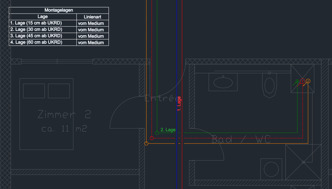
- 1 … 7 Everything is ordinary CAD lines, polylines and blocks with the data of Piping 2D – change them with the tools of the palette or with the GstarCAD commands.
More details
- Later the plan can be converted to 3D in Piping 3D – see On to 3D.
10. Changing it afterwards
You change it like a CAD object – crossings, elevation changes and neighbors adapt.
Change it with a grip
- Click the pipe – the GstarCAD grips appear at the start, in the middle and at the end.
- Click an end grip, drag it and click at the new location. The pipe becomes longer or shorter; if other pipes end there, their ends move along.
- Crossings, elevation changes and symbols follow by themselves when the command ends. More under Editing with grips and GstarCAD commands.
Move
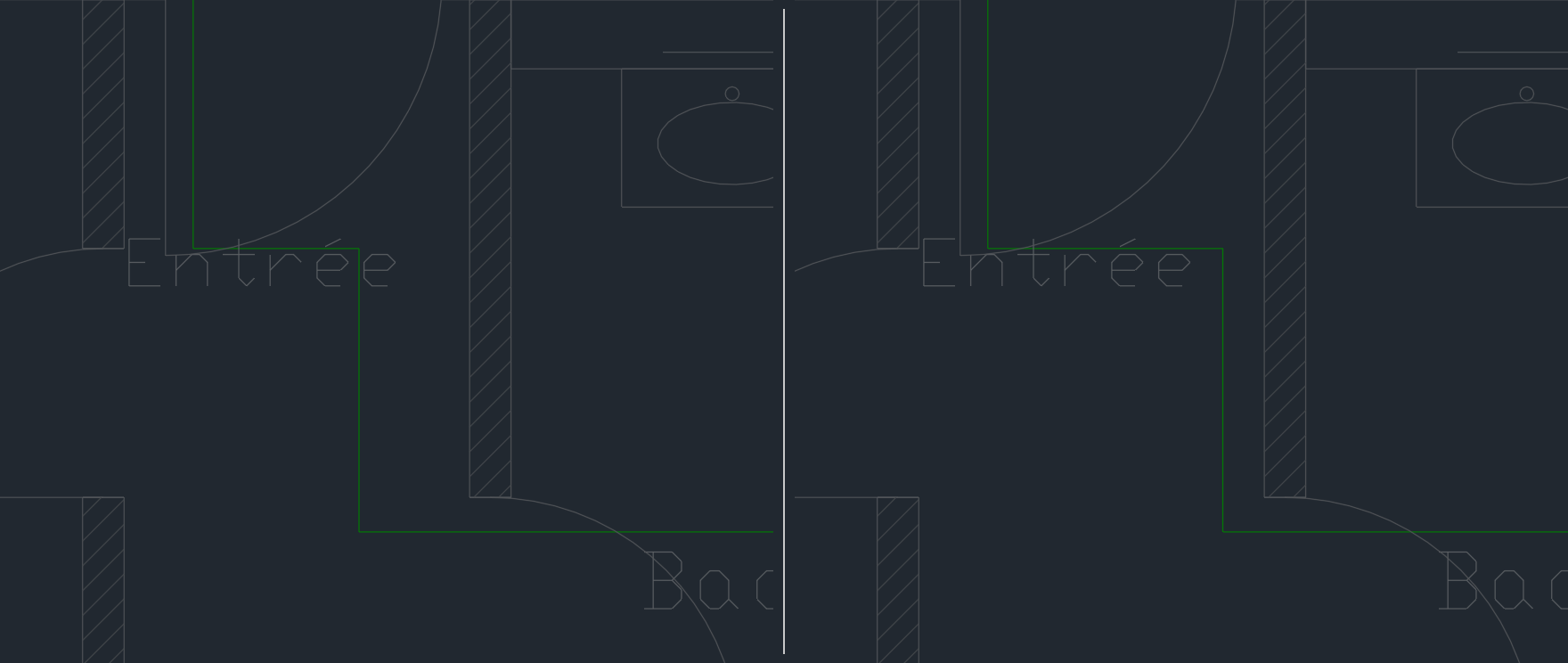
- In the tools at the bottom click Move and click the pipe 1; Enter.
- Click the new location – or press A and type a distance, for example 250.
- The neighbors are shortened, extended or joined again 2. More under Move; the GstarCAD commands (MOVE, grips, STRETCH …) work the same way.
Change the system elevation
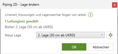
- In the tools at the bottom click Change system elevation and select the pipe; Enter. The dialog box shows 1 the number of selected pipes and 2 their current system elevation.
- 3 Choose the new system elevation – the one from the palette is proposed – and 4 OK.
- The pipe gets the linetype of the new system elevation; gaps at crossings and elevation change circles follow by themselves. More under Changing the system elevation.
On to example 2
The video shows example 1 once more as a whole; then continue with these pages.
- Example 2 – A piping plan step by step: parallel pipes in the corridor, connectors with a flexible pipe, manifold with PEX, editing with Connect and Break, symbols in the pipe.
Other ways
- Bendable pipes with rounded corners: Flexible.
- A valve in the pipe: Inserting a symbol.
- Esc cancels any function; another button in the palette cancels the running command and starts the new one. A U undoes the last step.