
Systems and layers
A system says what flows in a pipe or duct – cold water, heating supply, supply air, foul water. It decides which layer a part is on and how it looks. All systems are kept in one place, the system definitions; they are the same in Piping 3D, Piping 2D, Drainage 3D and Ventilation 3D. LuaCAD creates its layers itself by a fixed scheme – and leaves every layer that already exists exactly as you set it up.
What a system is
| Part | Meaning | Example |
|---|---|---|
| Abbreviation | The code by standard; shown at the part and in annotations. Several systems may share it, and it may be empty. | VL, PWC, SUP |
| Description | Abbreviation and description together are the name of the system ("abbreviation-description") – it must be unique, because it is also the name of its layer. | VL-Heizung, PWC-Kaltwasser reduziert |
| Discipline | Decides where the layer stands in the layer list: LuaCAD_<discipline>_<name>. | HZG → LuaCAD_HZG_VL-Heizung |
| Plug-ins | In which plug-ins the system is offered. | Ventilation 3D only |
| Display | Layer, color, linetype, lineweight and – for bodies and insulation – transparency, per part of the system ("display entry"). | centerline fixed color 7 |
Each system also has a fixed ID. It is created when the system is created and never changes – not even when you rename the system. So all parts in your drawings keep their system.
By default there are 55 systems: 32 for Piping 3D and Piping 2D, 13 for Drainage 3D, 10 for Ventilation 3D.
Display entries: the look per part
A system draws several parts: the routing line, the body, the centerline, the insulation … Each of these display entries has its own display. Which entries the system definitions show depends on the plug-in you open them from. Each entry is on one of three layers of the system: the base layer (LuaCAD_HZG_VL-Heizung), the layer …_Achse (centerline) or the layer …_Dämmung (insulation).
| Plug-in | Display entry | What it draws | Layer | Default |
|---|---|---|---|---|
| Piping 3D | Routing line | The routing line; a newly created base layer gets its values. | base | ByLayer |
| Piping 3D | Centerline | The axis of pipes and fittings. | centerline | fixed color 7, linetype CENTER |
| Piping 3D | Body | Pipes and fittings (layer, color, transparency only). | base | ByLayer, transparency ByLayer 0 % |
| Piping 3D | Symbol below, symbol above, symbol straight | The rise/drop symbols down, up and straight. | base | ByLayer |
| Piping 3D | Symbol axis | The axis of the symbols. | centerline | fixed color 7 |
| Piping 3D | Insulation | The insulation shell. | insulation | ByLayer, transparency ByLayer 80 % |
| Drainage 3D | Stack down, stack up, fixtures | The connectors of this kind. | base | ByLayer |
| Drainage 3D | Plumbing line and connectors | Plumbing lines, vents, offsets, spot elevations. | base | mostly ByLayer, three systems fixed |
| Drainage 3D | Pipe axis | The centerline of pipes and fittings. | centerline | fixed color 7 |
| Drainage 3D | Body PE | Pipes and fittings made of PE; a new base layer gets its values. | base | ByLayer |
| Drainage 3D | Body sound-insulated | Pipes and fittings of the sound-insulated product lines. | base | ByLayer (like body PE) |
| Drainage 3D | Insulation | The insulation shell. | insulation | ByLayer, transparency ByLayer 80 % |
| Ventilation 3D | Body | Ducts, round ducts, fittings and their preview at the cursor; a new base layer gets its values. | base | ByLayer |
| Ventilation 3D | Centerline duct, centerline round duct | The axes. | centerline | fixed color 7 |
| Ventilation 3D | Duct accessories | Grilles, dampers, sound attenuators … | base | fixed gray |
| Piping 2D | Single-line (2D pipe) | Pipes, rise/drop symbols, manifolds and symbols of Piping 2D. | base | ByLayer |
| Piping 2D | Riser insulation circle | The second circle of an insulated riser. | base | ByLayer |
The insulation of Ventilation 3D does not take its color from the system but from the insulation table.
ByLayer or fixed
Each property of a display entry is set in one of three ways:
| Setting | What the part gets | When useful |
|---|---|---|
| ByLayer | The property follows the layer. Change the layer in the GstarCAD layer manager and every part on it changes at once. The value next to it is the value LuaCAD uses to create a missing layer. | Color, linetype and lineweight of the routing line and the body – one layer, one color. |
| fixed | The value is stored at the part; a change to the layer has no effect. | The centerline in color 7 (black on white, white on a dark background) on a red layer. |
| from CAD (empty) | The current settings of the drawing at the time of inserting: the current layer, the current color. | Rarely – a new system that is not set up yet looks like this. |
Transparency exists only for bodies and insulation: 0 % = opaque, 90 % = almost invisible, in steps of 10 %. With the check box ByLayer the part shows the transparency of its layer.
Opening the system definitions
| Plug-in | Location |
|---|---|
| Piping 3D, Drainage 3D, Ventilation 3D, Piping 2D | Gear menu › Settings › Systems |
There is no button of its own on the ribbon. Block Library, Floor Heating, Openings and Annotation have no system definitions: Floor Heating sets its look in the gear menu › Display, and which system the connectors of a standard fixture get is set in the Block Library – systems of fixture connectors.
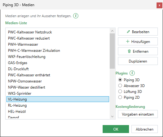
- The list shows the systems of the plug-in selected under Plug-ins – by default the plug-in you opened the system definitions from. Double-click edits a system.
- Edit, Add, Remove and Duplicate work on a working copy: OK saves all changes at once, Cancel discards everything.
- Every field and button: Reference.
Changing the color of a system
Goal: a system gets a different color – for new parts and, through its layer, for all parts of the open drawing.
- Open gear menu › Settings › Systems.
- Select the system and click Edit (or double-click).
- Choose the Attributes tab. Each row is a display entry; the button shows what applies ("ByLayer |
LuaCAD_HZG_VL-Heizung", with the color swatch of the layer). - Click the button of the display entry – the attribute dialog box opens. Click Color, choose the new color in the GstarCAD color dialog box, OK.
- OK in the dialog box of the system, then OK in the system definitions.
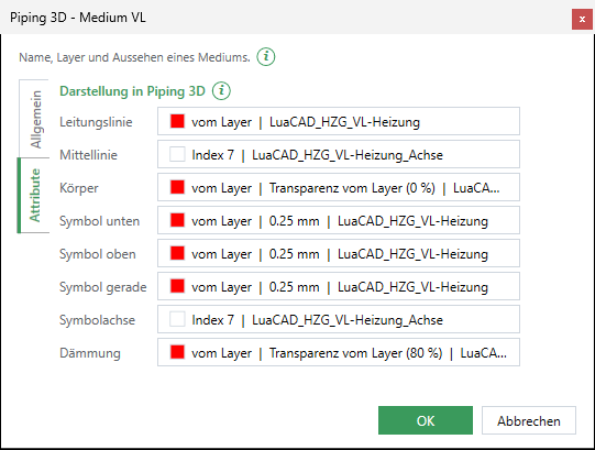
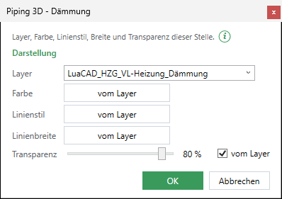
What happens to the layer: if the color of a display entry was ByLayer and you explicitly choose another one, the new value goes to the layer of the open drawing when you click OK in the system definitions, and the entry stays ByLayer. The command line reports which layers were updated. This applies only to the entry whose values the layer carries – the routing line in Piping 3D, body PE in Drainage 3D, the body in Ventilation 3D – and in the same way to linetype and lineweight; for body and insulation also to transparency ByLayer. If instead you choose the color of the body in Piping 3D or of a rise/drop symbol, it is fixed at that entry and the layer stays.
Creating a new system
Goal: a system that does not exist by default – for example a separate kitchen exhaust in ventilation.
The easiest way is to duplicate a similar system: the copy takes over its whole display and gets its own ID and its own layers. A system created with Add starts empty instead (abbreviation Neu, description Neues Medium, discipline general, every display entry from CAD, so without a layer) – you then set up each entry yourself.
- Open the system definitions from the plug-in that will use the system (here Ventilation 3D).
- Select a similar system and click Duplicate. The copy is named like the original with a number at the abbreviation:
ETA-AbluftbecomesETA[1]-Abluft. - Edit the copy: General tab – abbreviation, description, discipline, plug-ins (field by field: Editing a system).
- On the Attributes tab adjust the display entries – as in Changing the color of a system.
- OK, then OK in the system definitions. The system appears at once in the System list of the palette.
Editing a system field by field
General tab:
| Field | Effect | Example |
|---|---|---|
| Abbreviation | Code by standard; may occur several times and may be empty. | VL |
| Description | With the abbreviation the name of the system and its layer. | Heizung |
| Remark | Free text. | Vorlauf |
| Catalog system group | Assigns the system to the groups of the manufacturer catalogs (heating, domestic water, ventilation …). | heating |
| Substance | Liquid or gas. | gas for compressed air |
| Discipline | SAN, HZG, LUE, KAE, ELT, BRS, ALG – or "without layer – current layer": then the system has no layer of its own. | HZG |
| Plug-ins | Piping 3D, Drainage 3D, Ventilation 3D, Piping 2D – where the system is offered. | Ventilation 3D only |
| Cost breakdown › eBKP-H | The cost breakdown code for pipes, fittings, valves and insulation of this system; empty = default, "-" = explicitly none. | D05.04 |
Attributes tab: one button per display entry (see Display entries). The shortcut menu of a button has Copy style (Ctrl+C) and Paste style (Ctrl+V) – this way you take over the display of one entry into another entry, another system or an annotation template. What the target entry does not know is dropped silently.
Systems of Piping 2D
Goal: show the pipes in the 2D plan in their own way – independent of how Piping 3D shows the same system.
Piping 2D has its own list in the system definitions. They are the same systems as in Piping 3D (same ID – annotation, schedules and the conversion to 3D stay the same), but with their own display: single-line (2D pipe) and riser insulation circle. Both are on the base layer of the system – the same layer as in Piping 3D.
- Piping 2D › gear menu › Settings › Systems. Piping 2D is selected under Plug-ins.
- Edit the system, Attributes tab, change the entry single-line (2D pipe).
- OK, OK.
| Function | Effect |
|---|---|
| First start of Piping 2D | All systems of Piping 3D are taken over into Piping 2D once, with the display of their routing line. After that you maintain the list yourself. |
| Take over from Piping 3D | Only in the Piping 2D list: fetches the systems of Piping 3D that are still missing in 2D – saved with OK. |
| Add, Duplicate | Created in the Piping 2D list, the system belongs to Piping 2D only. |
| Remove | If the system is also in a 3D plug-in, it only leaves Piping 2D (after a question); it stays there. |
The layers of LuaCAD
LuaCAD finds and creates layers by a fixed layer standard – the same in all plug-ins. The principle: you decide about your layers, LuaCAD overwrites nothing.
- Only what is missing: if a layer is missing, LuaCAD creates it silently; if the name is taken, with " (2)" after it.
- An existing layer is never changed – name, color, linetype, lineweight, plotting, off, frozen and locked are yours. The only exception is your explicit action in the system definitions (see Changing the color of a system).
- Renaming allowed: every LuaCAD layer carries an invisible layer key. Rename it in the layer manager and LuaCAD still finds it; new parts go on the renamed layer.
- Duplicates (for example after pasting from another drawing): LuaCAD silently keeps the older layer.
Layer names
| Kind | Scheme | Example |
|---|---|---|
| System, base layer | LuaCAD_<discipline>_<abbreviation>-<description> | LuaCAD_HZG_VL-Heizung |
| System, centerline | …_Achse | LuaCAD_HZG_VL-Heizung_Achse |
| System, insulation | …_Dämmung | LuaCAD_HZG_VL-Heizung_Dämmung |
| Connectors per discipline (not plotted) | LuaCAD_<discipline>_Anschlüsse | LuaCAD_SAN_Anschlüsse |
| Annotation per discipline | LuaCAD_<discipline>_Beschriftung | LuaCAD_HZG_Beschriftung |
| Groups | LuaCAD_<discipline>_<group> | LuaCAD_SAN_Apparate, LuaCAD_BAU_Aussparung |
| Auxiliary layers | LuaCAD_HLP_… | LuaCAD_HLP_Nicht löschen (do not delete) |
Codes in the name: SAN plumbing, HZG heating, LUE ventilation, KAE cooling, ELT electrical, BRS fire protection, ARC architecture, BAU openings, PLN title block and layouts, BES annotation, ISO isometric, IFC IFC import, HLP auxiliary, ALG general. A system can carry the disciplines SAN, HZG, LUE, KAE, ELT, BRS and ALG. The layer names follow the program language (German today).
A new layer of a system gets color, linetype and lineweight of the display entry whose values it carries (Piping 3D: routing line, Drainage 3D: body PE, Ventilation 3D: body); white and black are created as color 7. The insulation layer gets the transparency of the insulation.
When LuaCAD creates a layer
| Occasion | What is created |
|---|---|
| A palette opens, the drawing changes | The base layers of all systems of the plug-in and its group layers – without an undo step, the drawing does not count as modified. |
| A part is inserted | The layer the part needs (for example the centerline layer with the first pipe). |
| Gear menu › Layers › Create all layers of this plug-in | All layers the plug-in can use. |
Locked layer
If a part is on a locked layer, LuaCAD changes nothing about it – no moving, no rebuilding, no values, not even when updating after a CAD command. The command line says that the layer is locked, the part was not changed and the change was reversed. A part made of several objects stays whole. New parts are created on a locked layer as well, as with the GstarCAD commands.
If a new part lands on a frozen or turned-off layer, the command line says that the part is not visible.
Blocks
- Standard blocks of the Block Library: the insertion is on the layer of its group (
LuaCAD_SAN_Apparate, in 2DLuaCAD_SAN_Apparate_2D), its content on layer 0. - Own blocks get no LuaCAD layer: the insertion is on layer 0, the content keeps the layers, colors and linetypes of its DWG. More: Layers in the Block Library.
- Parts in a pipe (valves, manufacturer products, custom parts) are on the base layer of their system and keep their colors.
The LuaCAD drawing template
New drawings are created from the LuaCAD drawing template (LuaCAD.dwt, see Welcome window). It already contains the base layers of all default systems, the group layers of all plug-ins, the annotation layers per discipline and the layers of the layouts (title block, sheet border, viewports, survey origin). The centerline and insulation layers are created with the first part that needs them – or with Create all layers of this plug-in.
Creating all layers of a plug-in
Goal: have all layers a plug-in can use in the drawing at once – for example to set up an office template with your own names and colors.
- Open the gear menu in the palette of the plug-in.
- Under Layers › Create all layers of this plug-in.
- The command line tells you how many layers were created and that existing ones stayed unchanged.
Only missing layers are created: in Piping 3D for example the base, centerline and insulation layers of all systems, the annotation layers of the disciplines, the layers of the isometric and of the connectors. Every plug-in with layers of its own has this entry.