
Example 1 – A bathroom
From the empty floor plan to the annotated pipe in 3D: the bathroom of an apartment on the 1st floor of the sample project, with lavatory, toilet, shower and washing machine, the shaft at the top right. Each step has one sentence, one picture and the clicks – the light blue numbers in the text are the numbers in the picture above. Variants, notes and the standard are collapsed under "More details".
1. Open the palette
Level and system at the top of the palette apply to everything you insert afterwards.
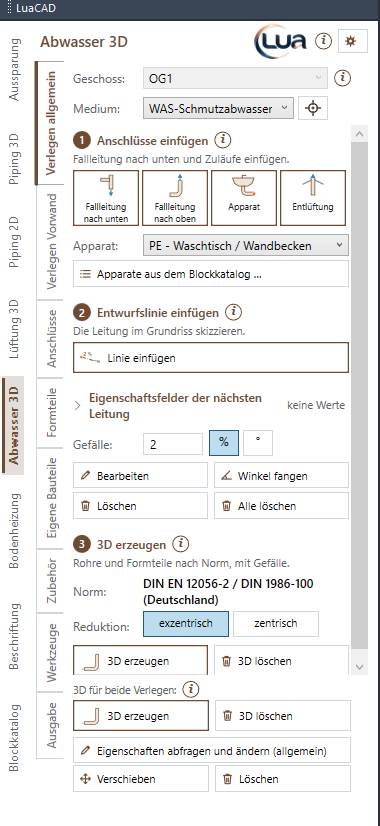
Ribbon › LuaCAD tab › Drainage 3D – the palette opens on the General routing page.
- 1 Level: in a project drawing the level of the drawing is already shown here, here OG1.
- 2 System: the wastewater system ("WAS").
- You need 3 4 in step 2, 5 in step 3 and 6 in step 4.
More details
- Level: the level you are drawing in. In a project drawing the list is locked.
- System: it sets layer and color. Lines of different systems or levels never connect.
- Leave everything else as it is for a start: slope 2 %, standard DIN EN 12056-2 / DIN 1986-100 as default (for Switzerland choose SN 592 000 under gear › Options › Sizing).
2. Insert the stack and fixtures
The connectors are the start and the end of the drainage network: the fixtures bring the water, the stack in the shaft takes it away.
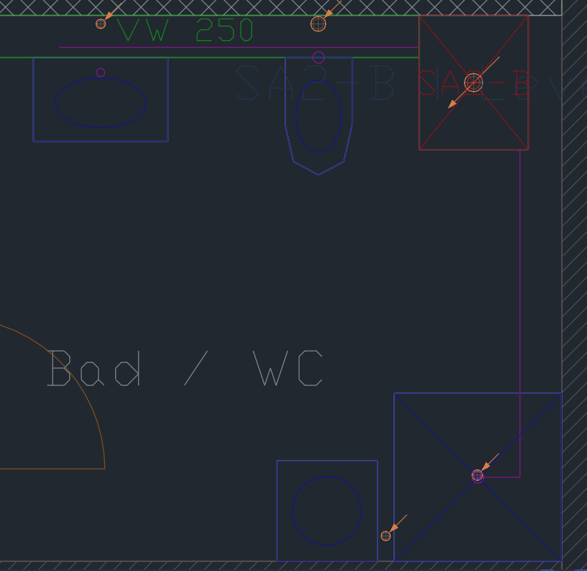
- 1 Click the Stack down tile and click into the shaft. After the click the dialog box of the stack opens – OK, then Enter.
- 2 In the Fixture list choose the lavatory template of the PE system, click the Fixture tile and click at the waste outlet; in the dialog box of the fixture OK.
- 3 The same for the toilet (6 l toilet template), 4 the shower (shower tray template) and 5 the washing machine (choose a template, in the dialog box short name "WM" and DU 0.8); Enter.
If a connector has to sit exactly, for example the lavatory with its center 300 mm from the wall: press A at the cursor and type the distance – see Enter distance (key A).
The dialog boxes when inserting
With the check box "Show the dialog box before inserting" (Connectors/Offset page, on by default) the dialog box of the connector opens after every click. For this bathroom OK is enough – the values come from the template.
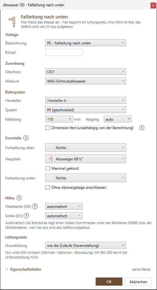
- 1 Stack pipe 110 mm, outlet "auto" – "Generate 3D" never sizes smaller than chosen here.
- 2 Main fitting "wye 88½°": through it the pipe enters the stack.
- 3 Invert "automatic": the elevation of the pipe at the stack; the slope builds up from here.
- 4 Property fields (description, tag …) – expand them only if you want to give values.
- 5 OK inserts the stack.
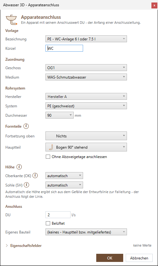
- 1 Description: the template all values come from. 2 Short name: appears in annotations and lists, here "WC".
- 3 Diameter 90 mm (minimum) and 4 main fitting "elbow 90° standing": what "Generate 3D" places below the toilet.
- 5 Elevation "automatic": the connector follows the slope of the line.
- 6 DU 2 l/s: the fixture unit the standard calculates with.
- 7 Property fields as for the stack, 8 OK.
More details
- The template brings the drainage fixture unit DU: lavatory 0.5, toilet 2.0, shower 0.6; for the washing machine you enter 0.8. Every field of both dialog boxes: Stack down, Fixture.
- Without the check box every click inserts the connector right away with the values of the template. You change values later with Edit (Editing connectors).
3. Draw the plumbing lines
The plumbing line only says where the pipe runs – a sketch in plan. You draw it from the fixture to the stack or onto a line that is already there.
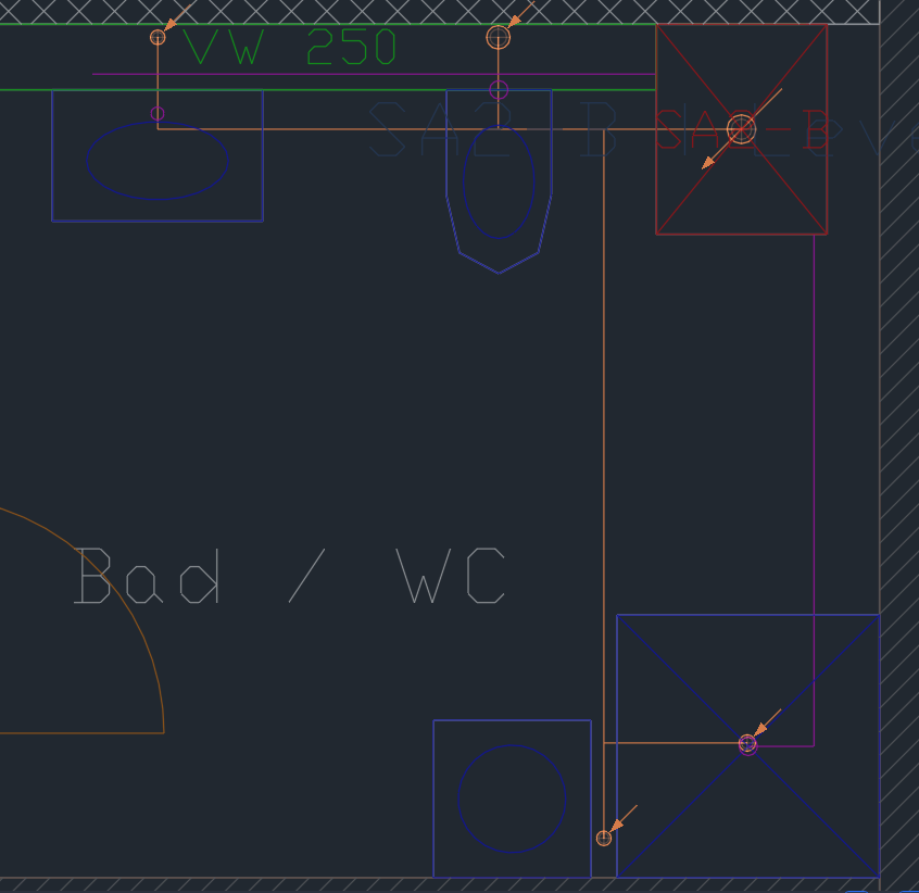
Click Insert line (step 2 on the palette), then:
- 1 start at the lavatory, 2 click the corner in front of the in-wall carrier, 3 click the stack – the line ends there by itself.
- 4 start at the toilet, 5 click onto the first line – it ends there, later a branch is created here.
- 6 start at the washing machine, 7 onto the first line.
- 8 start at the shower, 9 onto the line of the washing machine; then Enter.
More details
- The line snaps to the connector; a click on a connector or on a line ends it there. It is horizontal – the slope is a property and only takes effect in the next step.
- Exactly one line ends at the stack – all others meet a line that is already there.
- Space switches between snap to angle and free, A opens slope, elevation and wall offset while drawing. More under Inserting a plumbing line.
4. Generate 3D
The sketch becomes pipes and fittings – sized to the standard, with slope from the stack.
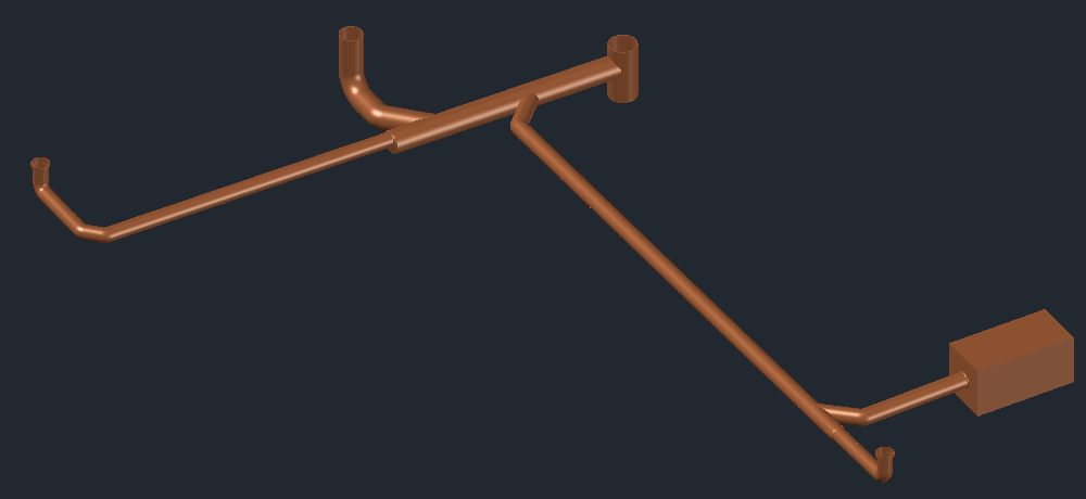
- 3 Click Generate 3D (step 3 or at the bottom in the footer) and click the stack – or Enter for all drainage networks of the drawing.
- 1 2 4 5 6 7 are created by themselves: pipes with 2 % slope, a 45° wye with elbow at each junction, below each fixture its main fitting.
More details
LuaCAD sizes the pipes to the standard, builds up the slope from the stack and places pipes, elbows, wyes and reducers from the catalog – in the product line of the stack (welded PE or a push-fit system, see Fittings). The plumbing lines and connectors then lie hidden under the 3D. More under Generate 3D.
5. Read the result
The window tells you whether everything was built and where each diameter comes from. It opens only if there is something to say – not with 2 % slope everywhere. In the picture the line of the washing machine is drawn with 0.5 %:
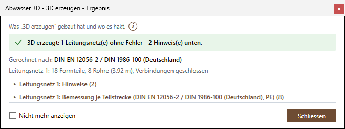
- 1 The header tells you whether there are errors (red) or notes (orange).
- 2 Which standard was used, 3 what was created in the drainage network.
- 4 Expand the notes – here: at 0.5 % the pipe needs a vent, it is sized as a vented pipe. Show shows the place.
- 5 "Sizing per section" says where each diameter comes from.
More details
- Everything about venting (missing vent, length, changes of direction, drop height or slope of a fixture drain) is a note, not an error: the 3D is created, and you decide whether to add a vent or route the pipe differently. An error (for example two stacks in one network) also appears as a red marker in the drawing.
- If LuaCAD suggests a different slope: Apply – it is set on the line and the network is generated again. More under The result.
6. Change: drag a line with its grip
You always change the sketch – then you generate the 3D again.
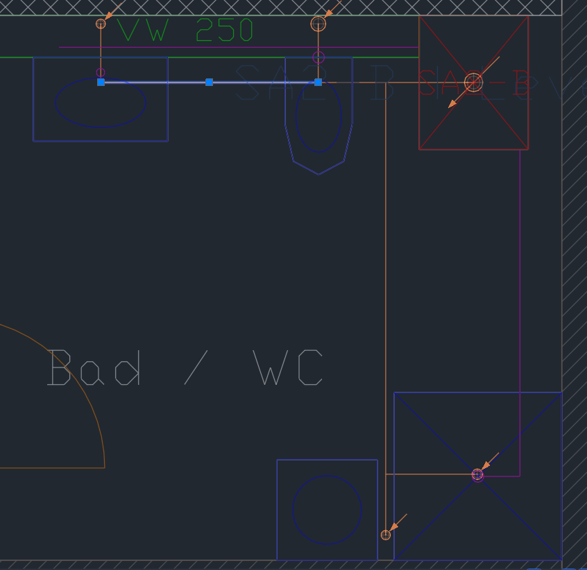
Delete 3D (footer) and click the network – the plumbing lines are visible again. Click a line, then:
- 1 3 an end grip moves only this end, connected lines follow.
- 2 the middle grip moves the whole line.
- Then Generate 3D.
More details
"Delete 3D" removes pipes and fittings, plumbing lines and connectors stay. The line shows grips at start, middle and end like a CAD line. The CAD commands MOVE, ROTATE and COPY work the same way. More under CAD commands.
Changing the slope of a line
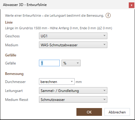
Click Query and edit properties (general) in the footer and click the line; Enter. In the dialog box:
- 1 length and elevations are only shown, 2 leave level and system.
- 3 change the slope, for example to 3 %, and click OK.
- 4 let the diameter "calculate".
Then Generate 3D – the network is created with the new slope. More under Editing a plumbing line.
7. Annotate and output the list
Material and diameter at the pipe, the slope as an arrow and the invert as a spot elevation – sparingly: once per pipe, at the fixture and before the branch. The bill of materials counts the parts.
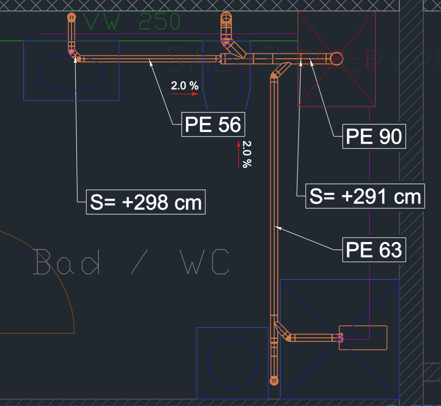
Output page, each time Single:
- 1 4 6 Annotation from template with the standard template "Material and diameter" ("Automatic" also takes it for pipes): click the pipe, place the text – "PE 56" = material PE, outside diameter 56 mm (without a known material "Ø 56").
- 3 7 Slope tile: click the pipe – the arrow lies along the pipe and points in the direction of flow.
- 2 5 Spot elevation tile: click the place, at the fixture and before the branch, then place the text. "S=" is the invert (choice "Spot elevation / elevation at" on the Output page, invert by default).
- Bill of materials: the table hangs at the cursor; click next to the floor plan.
More details
- With All and a click on the stack every pipe of the network gets an annotation – usually too many for a drawing; rather place them one by one at the start of the pipe and before every branch.
- Place texts so that leaders do not cross and no text covers another – a text can be moved with its grip.
- The annotation is attached to the pipe: after "Delete 3D" and generating again it finds its pipe again. More: Annotation, Spot elevation and elevation, Parts list and bill of materials.
Next: example 2
The video shows example 1 once more as a whole; then continue with these pages.
- Example 2 – A bathroom with an in-wall carrier: toilet and lavatory at an in-wall carrier, with a vent and a relief vent from fittings by hand.
- Example 3 – A horizontal branch: collect the stacks in the basement and lead them to the sewer outlet.
Other ways
- An in-wall carrier with toilet and lavatory in detail: In-wall carrier routing.
- Vertical parts by hand – a stack across levels, a double 45° bend: Fittings; together with "Generate 3D": Combining routing and fittings.
- Annotate diameter and slope, bill of materials: Annotation, Lists.
- Esc cancels any function; another button on the palette cancels the running command and starts the new one. U undoes the last step completely.