
Example 3 – An isometric in process piping
The workflow
A DN 50 pipe with a DN 40 branch, welded, with a ball valve – up to the sheet for the shop. You draw as in example 1; new are the pipe spec, the welds and the isometric. Variants are collapsed under "More".
- Choose the process piping catalog and a pipe spec
- Draw the pipe
- Insert the ball valve with a tag
- Create the welds
- Set the flow direction
- Output the isometric
1. Choose the process piping catalog and a pipe spec
Pipe page: catalog "process piping", below it the pipe spec (for example CS01 for welded carbon steel) and DN 50. The pipe spec defines which pipes, elbows, tees and reducers "Generate 3D" uses – and that they are welded.
More details
You create pipe specs under gear › Pipe settings; the specification controls, for example, which branch is made for which nominal size. See Changing a branch and the reference.
2. Draw the pipe
Insert and draw the DN 50 pipe point by point, then a branch: with Insert and DN 40, start in the middle of the first pipe – the reducing tee is created there. With "Generate 3D" as insert mode the pipes and fittings are there at once.
More details
How a run works in detail: Inserting a pipe; a pipe drawn as a routing line first gets its 3D with Generate 3D.
3. Insert the ball valve with a tag
Symbols page: "ball valve", Insert, click the pipe and choose the position. Then Valve › Properties, click the ball valve and enter the tag, for example V-101 – it appears in the isometric, the parts list and the PCF later.
More details
The tag exists only in the process piping catalog; it stays when the valve is rebuilt. A ball valve with weld ends gets a weld at both ends. More under Changing a valve.
4. Create the welds
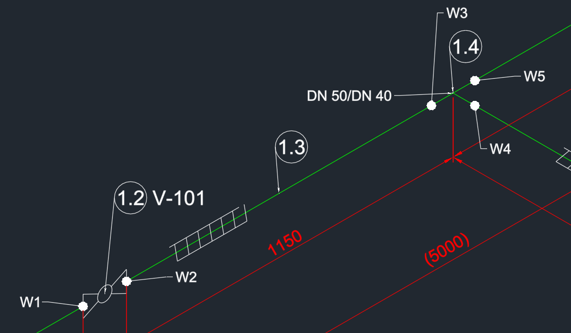
Fabrication page › Welds › Create and Enter for all pipes: every welded joint gets a weld – 1 at the ball valve, 2 at the tee. The isometric assigns the numbers W1, W2 …
More details
Set a field weld (FW) instead of a shop weld with Change; press-fit, push-fit or threaded joints get no weld. More under Welds.
5. Set the flow direction
Fabrication page › Define flow direction, click the pipe and point the arrow in the direction in which the fluid flows; click. The direction applies to the whole network of the same system – the isometric then draws its flow arrows and numbers the parts in this direction.
More details
Without a defined direction the isometric asks – it never guesses from the drawing direction. More under Flow direction.
6. Output the isometric
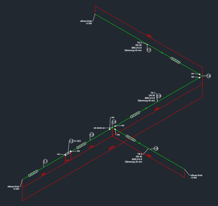
Fabrication page › Create isometric, click the pipe and choose the place for the sheet. LuaCAD draws the pipe isometrically, not to scale, with the true dimensions 1, the item numbers 2, the tag of the valve 3, the fittings 4, the welds 5, the insulation 6 and the elevations at the open ends 7.
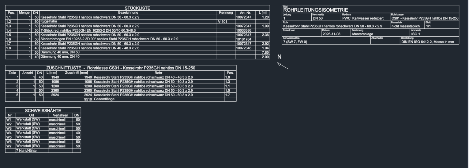
The sheet also shows 1 the parts list, 2 the cut list of the pipes, 3 the list of welds and 4 the title block.
More details
How every new isometric looks (scale, text, dimensions, lists, title block) is set under Isometric › Options. More under Isometric and The lists on the sheet; for fabrication in pieces: Spools, for pipe programs: PCF export.
Next
- Example 1 – A bathroom: from A to Z, with all dialog boxes while inserting.
- Example 2 – A distribution in the basement corridor: editing – connecting, nominal size, elevation, inserting in-line, issues.
- A branch taken straight out of the pipe instead of a tee: Extruded outlet.